Calibration of the IXPE instrument
The calibration equipment was designed and built at INAF-IAPS in Rome, Italy, for the calibration of the polarization-sensitive focal plane detectors on-board IXPE. Equipment includes calibration sources, both polarized and unpolarized, stages to align and move the beam, test detectors and their mechanical assembly
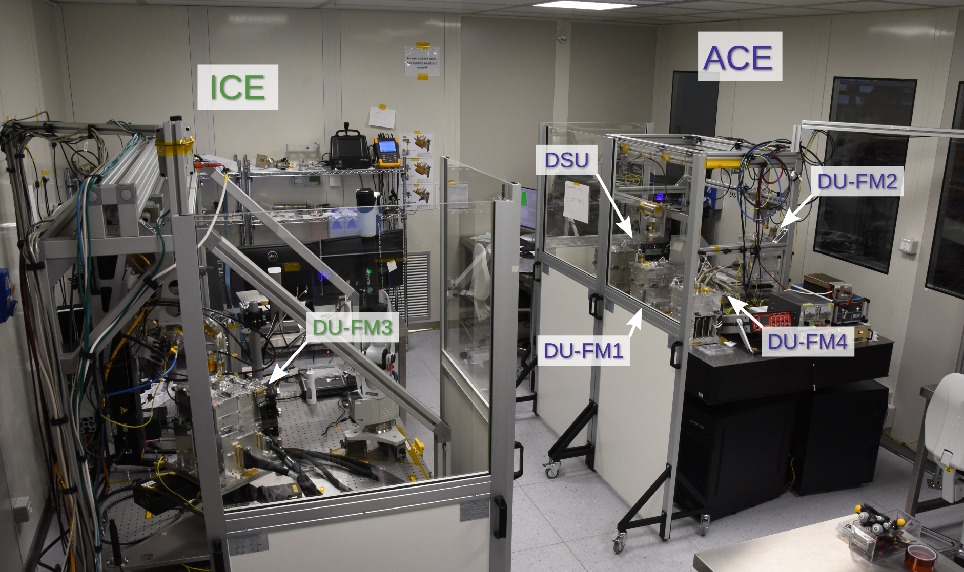
The focal plane detectors on-board IXPE are based on the Gas Pixel Detector (GPD) design, which have been developed in Italy for nearly 20 years by a collaboration of Istituto Nazionale di Fisica Nucleare (INFN) and Istituto Nazionale di Astrofisica/Istituto di Astrofisica e Planetologia Spaziali (INAF-IAPS) in Rome.
These detectors are the main Italian contribution to IXPE, which also includes the electronics to interface them to the spacecraft, the primary ground station and several contributions for the data processing pipeline, scientific analysis and data exploitation. IXPE polarimeters, named Detector Units (DUs), have been manufactured in INFN, whereas the Detector Service Unit (DSU) which interfaces them to the spacecraft was built by OHB-Italia. A flight DSU and four DUs have been produced, three for flight plus one spare.
The DUs and the DSU, comprehensively named the IXPE Instrument, were delivered to INAF-IAPS, including both the flight and the spare units, for extensive tests with X-rays before the integration on the spacecraft at Ball Aerospace, in Boulder, CO.
DUs were also integrated to the DSU and illuminated with X-ray sources to effectively test the operation of the whole IXPE Instrument in a configuration equivalent to the flight one.
Filter and Calibration Set
During the mission lifetime, the GPD response will be monitored using a filter and calibration set (FCS) hosted on a filter and calibration wheel (FCW) included in each DU.
Each FCS consists of four calibration sources, namely, CalA, CalB, CalC, CalD, and filters for special observations. The sets are denoted as flight model (FM)1, FM2, FM3, and FM4, and they are assigned to the three DUs that will fly onboard the IXPE spacecraft and one DU that will act as a spare.
The FCS includes both polarized and unpolarized calibration sources, capable of illuminating the whole detector or just a part of it, for mapping and monitoring of the GPD modulation factor (i.e., the detector response in terms of modulation to 100% polarized radiation), quantum efficiency, and energy resolution at different energies.
In-orbit calibrations will also allow us to check for the presence of spurious polarization, as well as to map and monitor the gain and its uniformity across the 15x15 mm2 detector surface. These information will help improve our understanding of the detector performance and asses the reliability of scientific results.
The calibration sources successfully assess and verify the functionality of the GPD and validate its scientific results in orbit; this improves our knowledge of the behavior of these detectors in X-ray polarimetry.
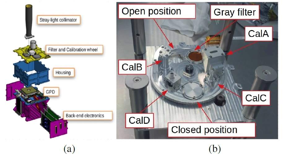
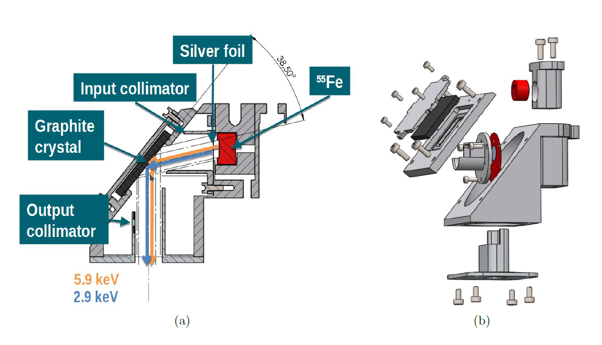
The FCS is composed of four calibration sources (a polarized source, CalA; a collimated unpolarized source, CalB; two uncollimated, unpolarized sources, CalC and CalD), a gray filter, and an open and closed position.
The FCS is hosted in the FCW which is placed on the top lid of the DU, as shown in the figure above. By rotating around its central axis, the FCW allows the placement of one of the four calibration sources or a gray filter in front of the GPD, in addition to the open and closed position, depending on the observational requirements.
The FCW also hosts other elements that ensure the stability and positional accuracy of the calibration sources. A rotary potentiometer is used to determine the wheel angular position accurately. Further, for redundancy, three radially placed Hall effect sensors and twelve magnets (positioned to realize a unique binary coding for the wheel’s seven positions) function as position reference points.
The calibration sources can thus be positioned with an accuracy greater than ± 500 μm with respect to their nominal positions. The angular position of the polarized calibration source with respect to the DU coordinate system is known with an uncertainty below 20 arcmin. The fixed parts of the FCW (e.g., the cover lid) are connected to the rotating parts (the wheel itself) by a bearing sub-assembly. Finally, a ballast mass is installed to balance the weights and the momentum of inertia on the wheel.
Each calibration source inside the FCW contains a radioactive source constituted of a 55Fe nuclide, which, following a K electron capture, emits X-rays at 5.9 and 6.5 keV, i.e., the Mn Kɑ and Mn Kɓ emission lines, respectively. The activity of 55Fe naturally decays with a half-life of 2.7 years, which provides sufficient time to cover the entire operative life of IXPE. This solution removes the problem of including X-ray tubes on board of the spacecraft, as their installation would have been complex, as well as mass- and power-demanding, especially on a moving support.
The items of the FCS were tested first with a commercial SDD and CCD to verify their operation. The calibration sources were then tested in TV with the flight DU to derive their spectra, images on the detectors, and polarimetric performance. The morphology of the sources, studied independently with CCD and GPD, are consistent. The expected counting rates are comparable across the different FMs, with differences that can be ascribed to the different energy resolution of each DU. The counting rates satisfy the requirements, and the modulation of the polarized sources is consistent with the one expected from Bragg diffraction.
The Instrument Calibration Equipment (ICE)
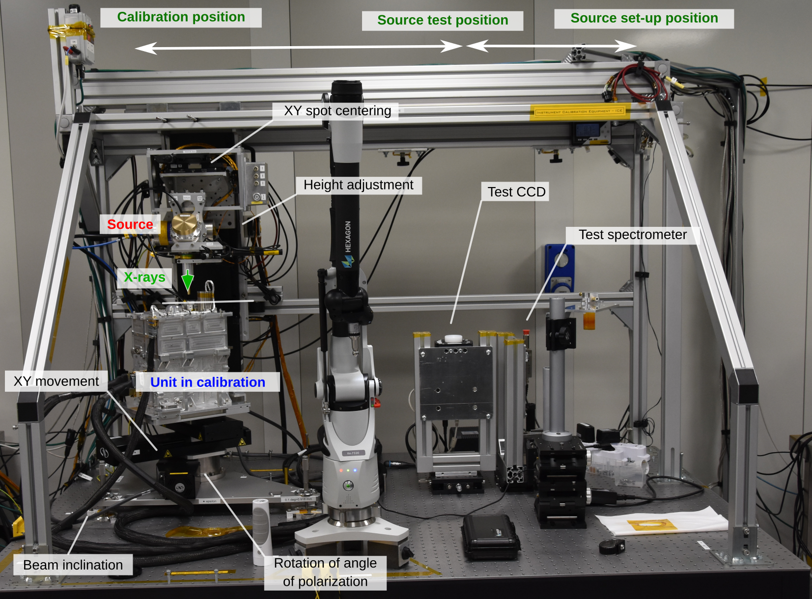
The Instrument Calibration Equipment (ICE) has been built at INAF-IAPS in Rome (Italy) to produce both polarized and unpolarized radiation, with a precise knowledge of direction, position, energy and polarization state of the incident beam. Inflight, a set of four calibration sources based on radioactive material and mounted on a filter and calibration wheel will allow for the periodic calibration of all of the three IXPE focal plane detectors independently. A highly polarized source and an unpolarized one will be used to monitor the response to polarization; the remaining two will be used to calibrate the gain through the entire lifetime of the mission.
The ICE comprises the items which are used for Instrument calibration and functional tests. In particular, it includes:
- The X-ray sources used for illuminating the detector. Each source emits X-ray photons at known energy and with known polarization degree and angle. The direction of the beam, the direction of polarization for polarized sources, and its position can be measured with respect to the GPD inside the DU and aligned and moved as necessary.
- The test detectors which are used to characterized the beam before DU calibration and as a reference for specific measurements (e.g., the measurement of quantum efficiency).
- All the electrical and mechanical equipment required to support the DU and the calibration sources, monitor the relevant diagnostic parameters and assure safe operations during calibrations. This includes also the clean environment (class better than 100,000) in which DU will be calibrated.
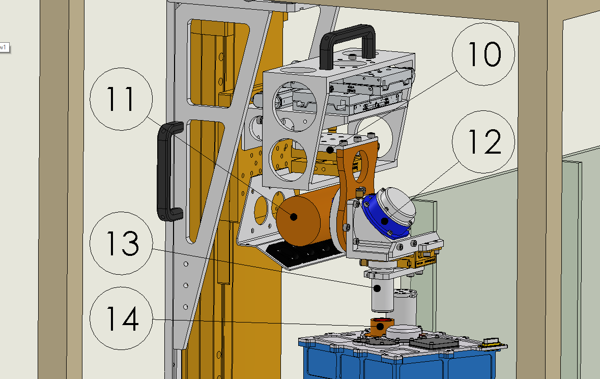
The DU will be mounted in the ICE without the stray-light collimator and the UV filter, to limit the distance between the X-ray source and the GPD and hence air absorption and beam divergence. The DU is placed on the top of a tower which allows to:
- Move the DU on the plane orthogonal to the incident beam with an accuracy of ±2 μm (over a range of 100 mm) to map the GPD sensitive surface.
- rotate the DU on the plane orthogonal to the incident beam with an accuracy of ±7 arcsec, to test the response at different polarization angle values and to average residual polarization of unpolarized sources, if necessary.
- Tip/tilt align the orthogonal direction of the GPD to the incident beam. Two out of the three feet of the tip/tilt plate will be manual micrometers, but one will be motorized to carry out automatically measurements with the beam off-axis of a series of known angles, between <1 degree and about 5 degrees, e.g., to simulate the focusing of X-ray mirror shells.
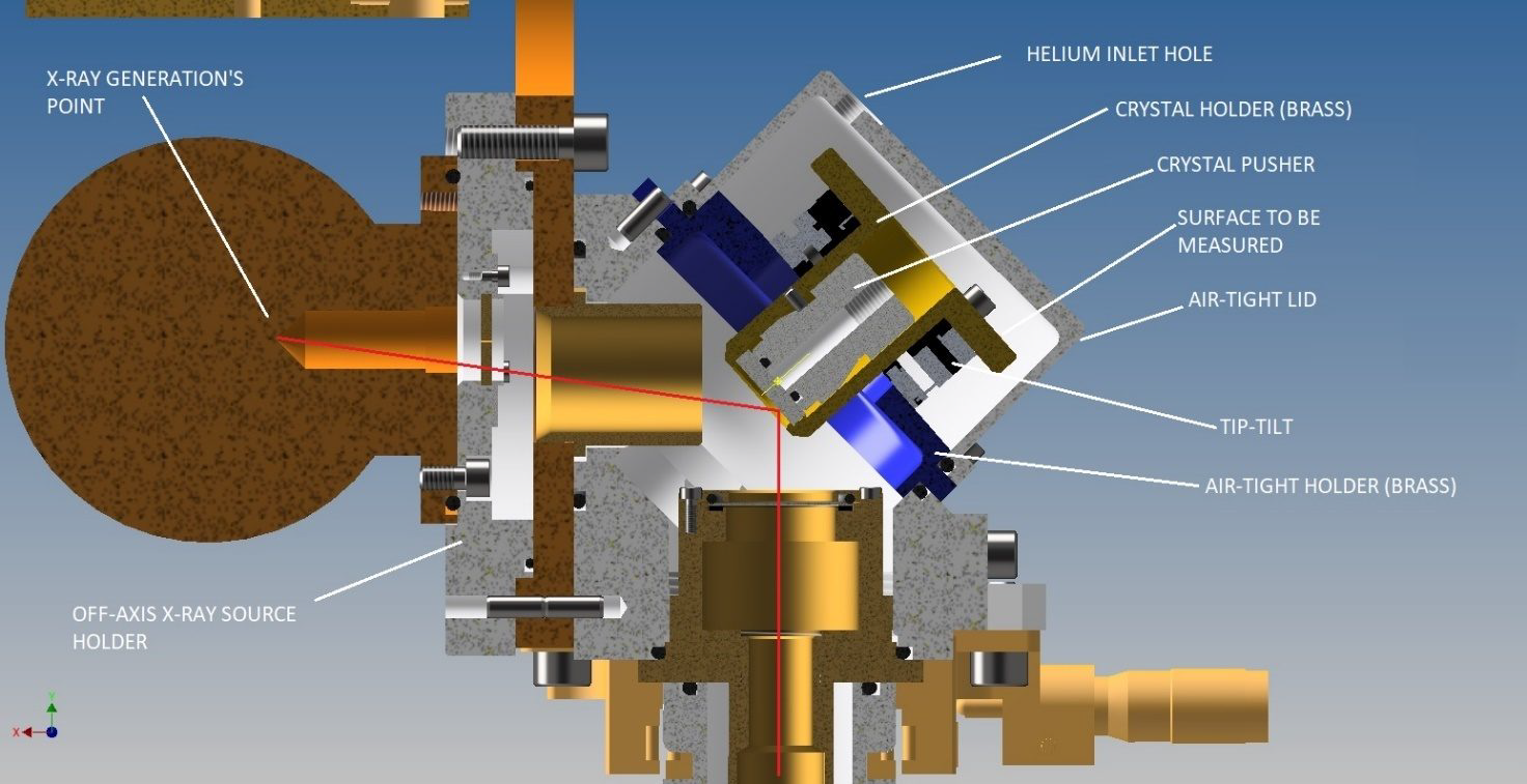
A cut-out and a detailed view of the polarized source with Oxford Series 5000 X-ray tube mounted is reported in the figures below.
 |
 |
Testing and characterization of the ICE sources will be carried out with three commercial X-ray detectors: (i) a CCD imager (model Andor iKon-M SY) to measure and map the beam spot and center the diaphragm of polarized source; (ii) a SDD spectrometer (model Amptek FAST SDD) to characterize the spectrum (and hence the polarization) and the counting rate of the beam. This detector will be also used as a reference for the efficiency measurements of the DU efficiency; (iii) a Si-PIN detector (model Amptek XR100CR) as a spare spectrometer.
IN-FLIGHT CALIBRATION
DU calibrations will be performed in orbit with the set of calibration sources mounted on the FCW with the aim of:- monitoring the modulation factor value of the GPD for monochromatic photons and hence the stability of polarimetric response at two energies;
- monitoring the energy resolution of the GPD;
- check for the presence of spurious polarization due to, e.g., any anisotropy in the distribution of the background;
- map and monitor the gain of the GEM and its non-homogeneities.
Calibration sources are hosted on a Filter and Calibration Wheel (FCW) which is included in the DU.
RESULTS
The items of the FCS were tested first with a commercial SDD and CCD to verify their operation. The calibration sources were then tested in TV with the flight DU to derive their spectra, images on the detectors, and polarimetric performance. The morphology of the sources, studied independently with CCD and GPD, are consistent.
The expected counting rates are comparable across the different FMs, with differences that can be ascribed to the different energy resolution of each DU. The counting rates satisfy the requirements, and the modulation of the polarized sources is consistent with the one expected from Bragg diffraction.
During the mission, the FCS will help validate the scientific results of IXPE by checking the detector response to point-like and extended sources. In summary, the results obtained on-ground, when extrapolated to the ones expected in flight, provide us with confidence that the FCS will be able to properly monitor the performance of the DUs.
Updated on October 15, 2021

