Gas Pixel Detector (GPD)
The GPD assembly — including the wire-bonding of the readout ASIC in its package and the positioning of the latter on the GPD board, the assembly of the gas cell, the metrological verifications and the initial leak test — was entirely performed in house, using a dedicated test setup at INFN and the calibration facility at IAPS. The assembly procedure was developed in collaboration with Oxford Instruments Technologies Oy in Finland (which also performed the final bake-out and filling of the detectors) and further refined through phases A and B of the mission.
IXPE will be the first instrument to perform spatially resolved X-ray polarimetry on several astronomical sources in the 2–8 keV energy band. These measurements are made possible owing to the use of a gas pixel detector (GPD) at the focus of three X-ray telescopes. The GPD allows simultaneous measurements of the interaction point, energy, arrival time, and polarization angle of detected X-ray photons.
The GPD, located in the GPD housing, is a gas detector for which the charge-signal is readout by a matrix of 105k pixels (300 352 pixels arranged in a 50 µm pitch hexagonal pattern) of a dedicated, custom CMOS ASIC.
The custom ASIC has self-triggering capabilities thanks to local triggers defined each group of four pixels called mini-clusters.
Each event consists of a Region of Interest (ROI) made by all the mini- clusters that trigger plus a selectable additional fiducial region of 10/20 pixels. The charge content of each pixel in the ROI is readout serially from a single buffer as differential current output by means of a 5 MHz clock.
The ASIC, also, provides the absolute position of the ROI as digital coordinates of two opposite vertices and the global trigger output, about 1µs after the arrival of the charge. The threshold is set low enough to collect signals coming from events which release about 300 eV. The charge amplification is provided by a Gas Electron Multiplier (GEM), a thin 50 µm dielectric (liquid crystal polymer) foil with 5-µm (TBC) copper metallization on both sides.
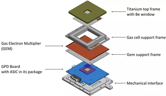
Through holes are laser etched and disposed on a regular triangular pattern with vertexes 50µm apart. These cylindrical holes have a diameter of 30 µm. The basic building blocks of the GPD assembly and their functions are schematically illustrated in the figure. The small pitch of the ASIC and the GEM are responsible for the good image of the photoelectron track.

In summary, the GPD is composed by the following subassemblies:
- mechanical interface (GPD Mech. I/F), made of titanium, which supports the GPD unit, connects it to the focal plane and provides references for alignment with the MMA;
- printed circuit board (GPD Board), which connects the GPD to the readout electronics;
- ceramic spacer (GEM Support Frame), supporting and insulating the GEM from the GPD Board; this item defines a lower gas gap of 500 µm for the drift of the amplified electrons.
- the GEM foil (GEM), including four soldering pads for the high voltage connections;
- ceramic support (Drift Spacer), which defines the absorption gas cell above the GEM and isolates the GEM from the top electrode;
- titanium frame (Ti frame and Be window) which closes the gas cell and allows X-rays into the GPD through the integrated thin, optical-grade 50 µm one-side aluminized beryllium window. The titanium frame and the beryllium window serve, also, as a drift electrode;
- filling tube of OFHC copper and its fixture to the titanium frame (tube and fixture);
The GPD is sealed and does not require any gas cycling systems. The keystone of the assembly is the Kiocera package. In fact the ASIC is designed to fit into a commercial package that acts as the bottom parts of the gas cell and connects the internal wiring and the clean gas volume to the external Printed Circuit Board (PCB), onto which the package is soldered.The GPD assembly is done at INFN, whereas the filling procedure is performed at Oxford Instruments Technologies Oy (OIT, ESPOO, Finland).
The performances of the GPD are, in principle, dependent on temperature to some extent. The GPD temperature is controlled during the operation by means of a Peltier cooler and a heater. A thermal strap connects the cooler directly to the spacecraft radiator. The GPD thermal control is performed directly by the DSU and is designed to be as independent as possible from the BEE temperature, since the latter has much looser requirements.
Detector Characterization
INFN produced 9 flight GPD—out of which four were chosen to be installed in the (three plus one spare) Detector Units (DU). All of them were extensively tested to verify their basic performance as focal-plane detectors using a dedicated test setup at INFN and the calibration facility at IAPS later used for the calibration of the DUs. We found all the detectors to show very similar performance metrics.
Updated on September 7, 2021

